BTS USMRR House Car No. 1 Build
While going through some of my old images, I came across the following images of a USMRR house/box car kit that Bill over at BTS (www.btsrr.com) gave me to test build. Before he offered it to the general public, he wanted me to build one and send him my feedback on the kit and its instructions. I photo documented the construction much better for this project than for my ventilated box car build so thought I would share selected images from the project here on my blog. According to the image data, I began the build in November of 2004.
Below is a photo of the kit's contents. It consists of laser cut wood and paper plus a bag of detail parts. At this point I had given the parts that were to represent unpainted wood a wash of black India ink & alcohol stain. Today I would go with a wash of Folkart brand #936 Barn Wood acrylic craft paint. You can buy this brand of paint at Michael's Craft Stores; possibly other craft places as well. I left the parts in their sheets to reduce possible warping and allowed them to dry between 2 sheets of 1/4" plate class to ensure flatness.


Lightly sand the edges of laser cut parts to ensure squareness. The laser cutting process leaves a slight bevel that is noticeable in thicker parts like those pictured and can result in parts not fitting properly. This is especially important in assembling parts that will be covered with a sheathing such as in this box car's case.
Once the 2 end/side assemblies dried overnight, I glued them and the floor joist/underframe assemblies together as shown below.The floor is inserted by angling it in. You insert the protruding floor boards on one side into its respective opening and then lower the piece into place. Please note the holes in the floor through which the nylon filament (fishing line) that represents the truss rods will be fished.
Below, I am using the magnets once again to hold the floor in place while the wood glue dries. I am also gluing on the truss beams seen below the car body proper.The floor boards extending through the door opening is intentional. The sheathing still needs to be glued on before these are sanded flush with the final door opening. I did lightly sand the edges of the sides and ends to make sure there were no protrusions that would interfere with gluing on the sheathing.
My hi-tech jigs to ensure the bolsters are correctly placed on the underframe.Next came gluing on the side and end sheathing.While the sheathing was drying, I moistened/soaked the sub roof and let it dry in my homemade "arched roof" bending jig. I am not sure where the 2lb. coffee can came from as no one in my household drinks coffee but it is the perfect diameter on which to bend USMRR arch roofed house car roofs. LOL I have since actually scrounged up better (wider) rubber bands for doing this.
The kit's brake platform is glued in its slot in the body. The white pieces are the beginning of my first detour from the kit instructions. They are 3 scale inch pieces of scale 1"x2" that will represent cast iron brake platform supports. I use Testors liquid cement to glue styrene to wood. It softens the plastic and allows the plastic to snuggle into the wood grain. To reinforce this bond once the Testor's has dried, I follow up with a sewing needle eye of super glue wicked in. The end beam and bumper blocks have also been glued in place per the kit instructions.
Below, I have threaded the fishing line through the holes in the car body and the turnbuckles. I use a #80 drill bit to ream out the holes in the turnbuckles before attempting to thread the fishing line through them. It makes the job of threading the fishing line much, much easier.


It may be hard to see, but to install the fishing line you first make a knot in one end. Being retentive, I use 2 knots and a drop of superglue before threading. You thread the line down through one of the outside holes in the floor from inside the car body and pull it tight. I use another small drop of superglue applied to the knot inside the car body for insurance before proceeding. Next you run the line through one of the turnbuckles, over the two truss beams and then up through the car floor. Pull it tight again. Do not let it go over your queen post if you are using them. Move to the next hole inside the car and thread the line down through it. Repeat the process until you have completed all 4 truss rods. Make sure the line is taunt then superglue where the last truss rod came up through the body. I bend the nylon line at a 90 degree angle parallel to the floor boards where it comes through the last hole in the floor and superglue it in place. I use a chisel point in an Exacto handle to do this so I don't superglue my finger to the car floor. (Experience speaking here.) Finally, I cut off any excess line. With BTS kits, I have gotten enough line to do at least one more car with each kit I've built. I have been able to scratch build/kitbash at least a dozen kits with the line leftover from the BTS kits I've built. Thank you, Bill.

The second deviation from the BTS kit instructions is seen below. Rather than just install the nuts that came with the kit, I decided to make my own side truss plates. I cut a piece of scale 1x4" to fit inside each of the lasered in plates on the car sides. Next, short piece of HO scale 2x2' were glued on upright so that the squares were evenly spaced on the plate. I allowed these to dry overnight. Sanding the 2x2s to about one scale inch in height came next. These are to represent the nuts anchoring the side to side trusses. Again, allow the scale 2x2" to dry AT LEAST overnight before sanding and use the fine side of the emery board and a light touch. If your pieces of 2x2" are on the long side, you might first nip them off closer to the side of the car with a flush end nipper before beginning the sanding. Next, I drilled holes in the center of each nut and inserted the left over sprues from the plastic Tichy Train n/b/w casting that came with the kit. When dry, these were cut shorter and sanded down to represent tie/truss rod ends.

After looking, and looking, and looking at the thus far assembled car, I decided to deviate from the kit instructions once more and replace the BTS laser cut truss bearing plates with 3" queen posts from Grandt Line. Below is an "in process" photo as the bearing plates were coming off.
It was relatively easy to do this using an Exacto chisel blade. After I chiseled off the bearing plates but before I sanded the beams smooth, I drilled mounting holes in which to insert the Grandt Line 3" queen posts. I did this before sanding as it was easy to drill the holes centered in the spot left by the chiseling process.
A couple of steps are recorded in the following photo. First, 1x2" styrene has been glued in for the second piece of the brake wheel platform support. Also shown, the buffer blocks and their n/b/w castings are glued in per Bill's kit instructions. I did not insert the kit supplied n/b/w castings in the 2 holes on each end of the end beam as I planned on making oval washers as seen in prototype photos of a large number of USMRR box cars.
Returning to the underneath of the car, pictured below is the simple styrene jig I made to sand down the bolster blocks so they are uniform and even.
A closer view of the jig. I test fitted the trucks and couplers I was going to use and estimated the height of the bolster I would need. It so happened that I had styrene scraps of about the right thickness available and used these to construct the jig.
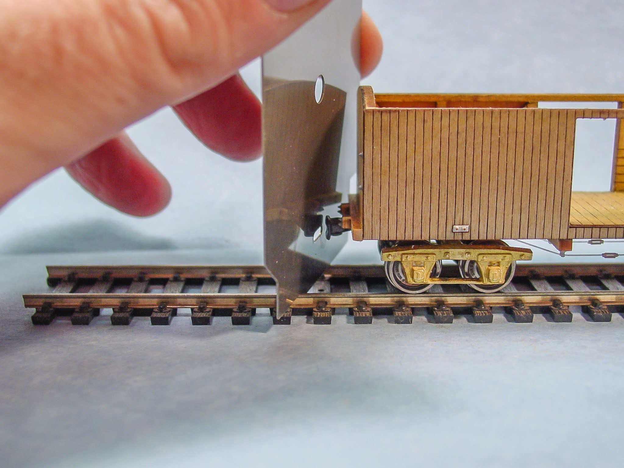
Next came trial and error. I sanded a little bit at a time until the opening of the draw head was centered in the opening of the NMRA coupler height gauge.
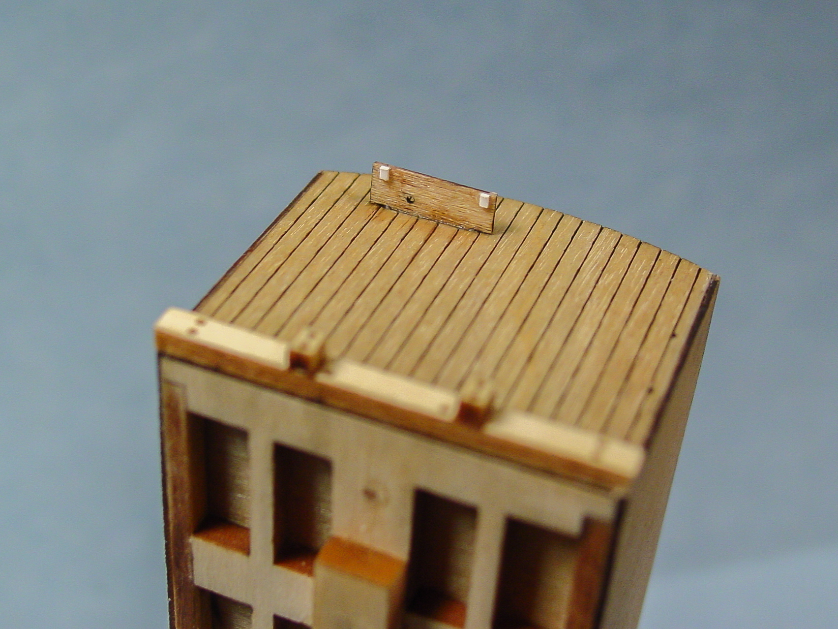
The final two 1x2" pieces of the brake platform support have been glued in place. They are a nominal 3 scale inches long. Also visible are the 2 n/b/w castings for the end grab iron.The BTS roof purlins glued in place per kit instructions. The 2 magnets in each end were installed so as to allow figures to ride on top of the finished roof. These magnets proved too powerful. They kept the figures in place but I could not operate 2 so modified cars running next to each other in a train without derailments. Also, trying to remove the figures sometimes resulted in picking the car off the track. I may experiment with less powerful magnets at some point; but probably not. This is the only car of mine that still sports the magnets. I have tried from time to time to dislodge them but attempts thus far have proved unsuccessful and I don't want to risk destroying the car in the process of magnet removal.
The now dry and formed sub roof being glued to the car body. The rubber bands insure a tight bond.
BTS ladder built and ladder and grab iron installed. Beginning of installation of roof walk supports.
Custom made oval end beam washers and bolts installed. The oval washers were sanded from Evergreen 1x4" strip. I made a go/no go jig to ensure the washers were all the same size and radius. I held the 1x4 strip in a fine tip locking tweezers and rounded off the end. The washer was then cut off to slightly longer than the finished washer. I then held the washer in the tweezers once again and rounded the opposite end. These were then glued to the end beams centered over the laser drilled holes in the kit. Once dry, I made 2x2" nuts using the same process as previously described for the side trusses.Grandt Line 3" queen posts installed. The turnbuckles are secured in place using a miniscule amount of superglue applied with the head of a modified sewing needle.Side view of same below.Even upside down, the magnets held the soldier in place and I could not shake him off of the car roof.Kit's paper framing glued to the doors.Doors glued to car body and upper door guides glued in place. Also, grey door stop made from half a Grandt Line stake pocket. You can also see the 1st step of the styrene door rollers I am making.The roof with roof walk and grab bars installed. Holes have been drilled in the roof walk to simulate nail holes.Part of a Tichy Train brake ratchet system glued underneath end beam for brake system roller.Another view of the end detail. This is the same detail as I applied in the ventilated box car build I did in a previous post.Once dry, the initial roller pieces are nipped off close to the bottom of the door and then sanded even with the bottom of the door using an emery board.After finishing the sanding, I took a scale 1x4" piece of styrene and cut it to the same length as the kit's lower door runner. I marked where to drill holes using a Stewart divider I got at an antiques auction, then laid the strip flush against the body and flush underneath the door and drilled out these holes so as to insert left over sprues from the kits n/b/w casting. Note that after the first hole was drilled, I inserted a sprue to help keep the styrene piece in place as I drilled the other holes. You could substitute Tichy Train 0.20 brass wire in lieu of the n/b/w sprues.


On the opposite side of the car, a bolt and nut have been run through a piece of cardboard slightly shorter but wider than the door opening. The bolt is then stuck through a piece of masking tape and held in place with a nut. I think this is a 1" long 2-56 nut and bolt. This assembly is carefully inserted in the door opening and then pulled tight up against the inside of the door.
First coat of Polyscale roof brown paint applied. USMRR house/box cars were described as a tobacco brown color. Roof brown is a close guestimate. This photo is a bit washed out. In person, the color is darker than it appears here. Also, not all USMRR house cars were painted this color as seen in period photos depicting lighter colored cars in service and E.L. Henry's painting of City Point, VA. More on that in another post.The opposite side also sprayed. Color in photograph is what the color really looks like in person.And a brake end view.Ready to paint the Polyscale grimy black roof and detail parts. The roof, grab irons, door handles, brake system, and wheels were all painted grimy black to represent a tin roof and cast iron hardware.Another end view.BTS arched roof house/box car on the left, Mantua horse car conversion on the right. Now decaled BTS USMRR box car on the right. My totally scratch built USMRR house car on the left. Both were sprayed with Polyscale roof brown. The car on the left is styrene, the car on the right is wood. The result is a desirable slight difference in coloration.Both cars on a diorama built by friend and commercial artist, Brian Kammerer. They are being pulled by an Akane 4-4-0 Texas.A closer view of the car.A slightly different angle.Since this was the 1st Civil War era piece of rolling stock BTS offered. And since this was the pre-mass production model. And since there is a photo in the digital holdings of the Library of Congress of USMRR box car number 1 at City Point. I renumbered this car as number 1. I also converted the couplers to Grandt Line Gilpin Tram On3 Link and Pin couplers. Here is the car photographed on my diorama on July 14, 2019. The car weighs in at 33 grams. Grams is a more accurate system with which to weigh rolling stock. This is about half the weight recommended by the NMRA but, with the brass trucks and all metal wheels, the center of gravity of this car is low and it runs well. My totally scratch built USMRR box car weighs in at 77 grams and meets the NMRA standard. The 30 to 45 gram range is good for those of us modeling the Civil War era. It allows for longer trains that still run well.The P&WV box car #69 on the left (36g) is from a resin kit my friend, Rev. LeBron Matthews, made of a Georgia RR prototype. P&WV box car #57 next to it (26g - more weight to be added) is a BTS kit of the same GRR prototype. Delaware Central box car 347 (37g) is a modified Mantua box car. It has been lowered per an online article by the late Harold Minkwitz and the unnecessay steel weight has been removed. Next comes USMRR box car #1 as discussed in this post. The last car, O&A RR 2031 (48g), was built by late friend Al Mueller from an Alkem Scale Models kit. Even though on the heavy side, I have no plans to modify Al's car as it reminds me of a good friend and a superb modeler.